Icom - IC-706
########################################################################
New yellow wire disconnect and reattachment to vco switch bank works!!!!!
This mod is great thanks for everyone's help out there!!
########################################################################
I have an Icom IC-706 and did the mod.
remove the yellow wire (4th from the edge of the plug in
connector ) on the top side of the IC-706 right above the FL-30
SSB filter. The yellow wire controls either switching in the
120Mhz LP filter or the 2 meter (pseudo HP filter).
If you just disconnect the yellow wire , the sensitivity
increases above the 148-200 Mhz region. I also noticed the FM
broadcast sensitivity went down greatly, to over come that, the
yellow wire routed from the top side back to the bottom side and
attached the VCO switch points (see note below). The +5Volts
logic high from the plated hole next to J8, allows the LP 120Mhz
to come back when the radio is tuned below 129Mhz.
I did this mod and it works great!!!!
As far as FM Broadcast intermod in the Aircraft band, I noticed
the IF is a little overdriven into compression, so I turn the
preamp off (greeen to no light---preamp switch), and noticed no
difference in sensitivity, intermod in aircraft band
disappeared.
Running the preamp in the Aircraft 118-129 does not really help
sensitivity, even though the S-meter shows higher signal levels
(jumps around allot due to saturating IF when signals are not
there!!! ) the noise floor actually, degrades, thus I leave the
switch (no preamp-black instead of green).
Leaving it on green is just fooling yourself, driving the IF
into saturation, with worst dynamic range.
I hope someone from Icom reads this, with this mod, now I can
say the rig now covers the 30Khz - 200Mhz, rather than the
modified statement 30Khz - 120 Mhz.
Now , I am very happy with the receive performance, leaving the
yellow wire, and not connecting it to the VCO switch bank logic
high point near J8, allowed me to hear 2 meter repeaters in the
82-83Mhz range, and poor FM broadcast reception.
Now connecting it to the VCO switch bank, the radio performs to
my satisfaction, hearin weather at 162, forestry at 171, TV audio
near 200Mhz and remembering to turn preamp off in 118-129
aircraft region, no 2 meter images/mixes any more in 82-83Mhz
area from 2 meters. Can comfortable listen now to FM broadcast
in the 88-108Mhz area. I now have no real complaints about the
the IC-706.
Having fun with mine, traded in my Kenwood TS-50, and no complaints,
don't even miss the TS-50. THe IC-706 is a real great rig.! Have fun
with your 706's .
ICOM, I HOPE YOU SEE THIS, I THINK THIS MOD IS VIABLE AND SHOULD
BE INCORPORATED FOR NEWER ICOM IC-706's!!!
73
Mike
W6TRW
(Cecil A. Moore~) writes:
The fourth yellow wire seems to control
a lowpass/highpass 120 MHz filter. In the standard configuration
the
highpass filter is used only on 144-148 MHz, every other
frequency uses
the lowpass. Anyway, if you want to listen to frequencies above
120 MHz
this mod is very useful. It does even remove most of the FM band
intermodulation. I just don't understand why Icom has not put
the switching
limit on 120 MHz instead of 144/148.
Does this mod affect HF or 6m? After the mod, what
frequencies use the LP
and what frequencies use the HP filter?
The mod affects only frequencies above 60 MHz. If you just cut
or remove the yellow wire, the HP or actually 2m band pass filter
is used all the time.
Last night I took the loose yellow wire and connected it to a
VCO control switch transistor (?) on the lower PC board. Now I
have the LP filter in use between 60 and 129 MHz and the 2m band pass
between 129 and 200 MHz.
There are five SMD transistors on the lower PC board just behind
the "MENU" button. The one in the middle controls the
VCO that is in use from 60 to 129 MHz. The single pin has 5V
when within this range.
There is a trace from this pin to a plated-through hole near J8.
This is a good place to connect the wire. (I haven't even seen
the schematic so cannot say if this is the best way to do it.
But it works for me.)
129 MHz seems to be quite close to the cross-over point of the
LP and 2m BP filters. Here is a listing of the (NBFM) signal
strength needed to "light" the first segment on the
S-meter on each frequency:
MHz     uV/LP     uV/BP
125     .8        2
135     12        .5
145               .15
155     30        .5
165               3
175               11
185               140
After the mod I can listen to the Helsinki
airport on 134 MHz but the Meteo on 128.4 is still drowned in
intermod from the FM BC band.
>thanks and 73, Cecil, KG7BK, OOTC (not speaking for my employer)
Neither am I. Proceed at your own risk
etc. And have more fun with the 706!
|
|
| |
IC-706
Expanded frequency |
|
| |
|
|
If you think to change your new little rig
into a UFO read following info. Read everything and wait.
"Notice : We can not guarantee specification when expand
frequency"
To find every detail you should have the service manual. At this
moment I have to deal with some bad copy's. I think they went
for 21 times into a Xerox copy.
By cutting diode D59 only, "nyea what's up doc?" does
not work.
So here are the results (read the above notice) to leave your
UFO on the table.
** Cut the D59 diode on main Unit. (TOP SIDE of P.C. Board) **
Where do you find this little thing?
If you can locate the Filter option place you will see in the
middle of the P.C. board 5 little things on one line and this is
what you're looking for. But white.
Maybe this can help you.
** If you have a USA-version you need additional modification.
**
** Cut D60 and jumper wire W4. **
Next lets find Q38 or R353 on MAIN UNIT (top side of P.C. Board)
You can find this when you are already in the rig, you have a
large metal cover (like a box, probably there is a lot of money
inside HI)
                +---------------+
                ¦               ¦
                ¦               ¦
                ¦               ¦
                ¦               ¦
                ¦               ¦
               -------------------
                ¦               ¦
                ¦               ¦
                ¦               ¦
                ¦               ¦
                ¦     --------  ¦
                ¦ *   .      .  ¦     *=Q38
                ¦     .      .  ¦
                ¦     .      .  ¦
                ¦     --------  ¦
                ¦               ¦
                ¦               ¦
                ¦               ¦
                ¦               ¦
                +---------------+
**Then you have to cut the P.C. board at a
certain point on the bottom side.**
It is not so far away from H2, H6 and IC 32
**And then you have to add a jumper wire from pin 11 of IC32 and
a certain
point on the bottom of the main unit......
So only cutting D59 this is a joke. I can even say a BIG joke.
To explain you the total modification you need a service manual.
In a few day's (around 100 HI) I'm able to put the schematics on
packet.
I will try and hopefully you can do something with it.
So don't jump around in your nice equipped shack, do not make a
UFO out of your new 706 just wait and I can see what I can do.
|
|
Dr Oms
If you can spare more than 0.3 Amps from battery on /p operation
switch off backlight of yellow display (Initial Set Mode, item
5.) This helps much, i have only abt 1.1 Amps for receive now I
did not find any info in the manual
Best of luck
|
|
| |
MARS/CAP
Modification for ICOM IC-706 |
|
| |
|
|
Tools required:
- #0 Philips head screwdriver
- 10 - 15 watt pencil tip soldering
iron
- Magnifying glass
- Tweezers
Remove the TOP cover by removing three Philips
head screws on the top and one on each side. Move the
speaker bracket out of the way. Locate D-59, this is a three
terminal SMD diode in an SOT package, about 1 x 3 mm (with the
radio front panel oriented towards you, D-59 is located in a row
of SMD diodes just to the right of the ribbon cable header above
the 9 MHz SSB filter FL-30. There are pads for 5 diodes with
only three installed. D-59 is the second from the left).
Using tweezers and a low-wattage soldering iron (and magnifying
glass, if necessary) remove D-59 by applying some heat to the
single leg side of the device while lifting gently, then apply
heat to the other two legs and removing the device. Be careful
not to apply too much heat, not to rip or burn any traces or not
to leave excess solder on the PCB.
Replace the speaker bracket and top cover. Apply power and reset
the microprocessor.
TX = 1600 kHz - 54.00 MHz and 118.000 - 174.000 MHz
|
|
ICOM IC-706 HF/VHF AMATEUR RADIO
TRANSCEIVER
Product Review, Hints and Tips, and Modifications
As Of: December 28, 1995
by Randall Rhea, KG0HW
Overall impression
"Too good to be true". This was my understandable
reaction to Icom's announcement of the IC-706 amateur radio
transceiver last summer. It looked like my dream mobile rig:
very small size, detachable face plate, all HF bands, FSK, 6
meters with 100 watts ... AND 2 meters, all in one rig? It
sounds too good to be true, but after using this radio in my car
for about a month, I can tell you that this radio is real.
Although the rig is not without its faults, Icom has produced an
innovative masterpiece. The rig does just about everything as
advertised. It is an easy-to-use radio that replaces several
other radios that I was operating in my car.
Over the Christmas holidays, I took a couple of long car trips
here in Texas. The 706 was installed under a car seat, leaving
plenty of room for luggage and packages. (Do NOT block the top
of the rig. Leave room for air circulation. The rig gets VERY
hot when transmitting!) The face plate was installed just below
the dash within easy sight when driving. I used headphones, so
my wife and daughter could listen to CDs while I was working DX.
The headphone plugged into the face plate. I used a 7-foot whip
mounted on the trunk of the car tuned for the SSB portion of 6
meters, my favorite band. The radio was a pleasure to use, even
while driving.
During a nice opening on 6 meters on the evening of December 27,
I worked several new grid squares in the midwest and Arizona. I
also worked North Dakota for the first time. I was able to work
a station in Mexico City quite easily, despite the pileup. That
100 watts sure helps. (I previously used a 10-watt rig.) The
sensitivity of the receiver, although not quite what the
"pros" would want, was quite adequate. Noise from the
car engine was only a minor problem; the noise blanker was
effective for SSB.
During the trip I also listened to a football game on TV channel
2, listened to truckers' traffic reports on CB channel 19
(27.185 MHz), worked a couple of 10m stations during the
sporadic E opening on December 27, worked a couple of 20m
stations, listened to WWV on 2.5, 5, and 10 MHz, eavesdropped on
some interesting baby monitors and cordless phones on 49 MHz,
listened to NOAA weather forecasts on 162.55 MHz, monitored some
aircraft traffic, and did some rag chewing on 2-meter repeaters.
Not bad for ONE radio!
PRICE
I paid $1249 for mine at Tucker Electronics in Dallas. They told
me that they have sold about 200 of them in six weeks, making
the IC- 706 their best selling rig of all time. They are getting
them from Icom in lots of 20 and are having trouble keeping them
in stock.
Prices for accessories are pretty high. There is little profit
margin in the box, so they make up for it with high accessory
prices. The cable to allow for front-panel detachment is $48.
UNIQUE FEATURES AND INNOVATIONS
See www.icomamerica.com/icom/amateur/hf/#IC-706
for a list of features.
- The smallest HF rig on the market
(similar in size to the Kenwood TS-50)
- Detachable face plate with a jack
for a speaker or headphone. The mic plugs into the face
plate using a plug similar to a modular telephone plug. (A
spare plug is included.) The cable to allow for this
detachment costs extra.
- Full HF/VHF transmit coverage from
1.6 to 54 MHz and 144-148 MHz (the rig transmits only on the
ham bands out of the box, but an easy modification unlocks
the transmitter, see below)
- General coverage receive from 50 KHz
to 163 MHz (requires modification, see below) Rig receives
up to 200 MHz but with poor sensitivity above 162 MHz even
with the modification. You will be able to receive: long wave,
AM broadcast band, short-wave broadcast, all amateur bands in
all modes from 160m to 2m, FM broadcast band (wide FM),
aircraft (118-136 MHz AM), VHF from 30 MHz to about 162 MHz,
US TV channels 2 through 6, NOAA weather at 162 MHZ.
- 6 meters and 2 meters, all-mode
- 100 watts on HF and 6 meters (10
watts on 2 meters)
- Innovative, easy-to-operate menu
system. It becomes quite easy and natural to use after
reading the well-written manual for about an hour. (In
contrast to my Yaesu FT-470 HT, which I still cannot figure
out.)
- The manual is very well written,
with lots of easy-to-understand diagrams.
- Simple, but useful and configurable
band scope. (Previously available only on very expensive
rigs like the Icom 781.) This allows you to examine nearby
frequencies for activity.
- Split frequency operation appears
complicated at first, but the rig's "quick split"
mode makes it fast and easy.
- Built-in electronic keyer at no
extra charge. The Up/Down buttons on the mic can be used as
a paddle. This has rejuvenated by interest in CW. I worked a
couple of slow CW stations on the novice portion of 80m,
which made me remember how fun CW is.
- FSK (Nice feature for this price
range)
- DTMF and programmable offset for
repeaters and split frequency work
- Good audio reports from contacted
stations. A station on 3.85 MHz reported "a very good
signal for a mobile". A 2m FM station reported
"very good audio ... so that's the 706 I've been
hearing about."
- Works very well with the AH-3
antenna tuner. This is the Icom HF (1.8-30 MHz) random wire
tuner that worked with the 725. The tuner is mounted under
the trunk lid of my car with cable ties. It can also be
mounted outdoors. It will tune any 8-foot whip or wire for
any HF band. (You need 40 feet for it to tune to 160m.) You
can press a button to enable the tuner, or the tuner can
fire off automatically if your SWR is too high. With my
7-foot 6-meter whip, I can tune to any HF band above 3.5
MHz. That means I need only one simple antenna for HF and
6m.
- 100 memories that store frequency,
split offset, mode, and FM tone.
- Two antenna connectors: one for HF/6m
and one for 2m. The connectors are switched at 60 MHz.
- Jacks for remote speaker and/or
headphones on both the face plate and the back of the rig.
- Multifunction meter: S meter, SWR,
relative power output, ALC.
DRAWBACKS/FLAWS
- Extended VHF receive requires
modification (see below).
- Poor sensitivity above 162 MHz.
- Noise blanker does not work on AM.
Very irritating pulse noise on AM while the car's engine is
on. The blanker works well on other modes (except FM, where
it is not needed). Not good for listening to AM while
driving. A rather serious flaw in my opinion, since my $40
CB has a noise blanker that works well.
- Poor QSK (full break-in) capability.
Not recommended for high-speed CW operators who want QSK.
Use semi-break-in instead.
- No CW narrow filter. You can install
one as an extra-cost option or use an external CW filter or
DSP unit.
- The built-in speaker provides
surprisingly good audio for its size, but you will probably
want to use an external speaker. The speaker can be
connected to the face plate or to the rig itself.
- Automatic repeater offset is not
programmed into the rig. You need to program -600 or +600
yourself through the menu system. This is not a problem if
you store your favorite repeaters into one of the 100
memories.
- The S-meter is inaccurate below S9.
Above S9, it is quite accurate.
- High prices for accessories (typical
of just about all other vendors)
- The AH-3 antenna tuner is shipped
with an unshielded cable, which picks up a lot of auto
engine noise. You need to make your own shielded 4-wire
cable. The AH-3 also blocks signals above 54 MHz. It also
only works for HF, not for 6m or 2m.
- Expect performance and receiver
sensitivity similar to other rigs in this price range. This
is a low-end rig in terms of price. For price vs.
performance, this is probably the best amateur radio of all
time. However, it will not outperform your $4000 rig. You
probably won't win contests with it. You will have a lot of
fun and own a nearly ideal rig for mobile work.
HINTS AND TIPS
- Take time to read the manual. The
menu system will be bewildering unless you read the manual.
One you get used to it, you will find the rig to be
amazingly easy and fun to use.
- You need to set the mode to wide FM
to receive FM or TV broadcasts. Tune to the station, press
the MODE key until the front display shows FM, then press
and hold the MODE key for 2 seconds. WFM will appear in the
display, and you will hear the station with nice audio.
- Don't use the noise blanker on AM.
It will not be effective and may distort your audio.
- Don't use the QSK feature.
- The rig gets very hot while
transmitting. Keep the top of the radio clear to allow air
circulation.
|
|
| |
Enables
out-of-band transmit for 1.6 MHz to 54 MHz |
|
| |
|
|
This does not enable extended VHF
transmit; a modification for this may be available soon. This
does not enable AM or FM broadcast band transmit. Your memories
will be cleared after this modification, since you need to reset
the CPU.
- Open the top of the radio by
removing the 3 top screws and 2 side screws. Look at the
radio from the with the front panel facing you. screws.
- Gently pull up the speaker and set
is aside without damaging the speaker or the wires that
attach it to the rig.
- Note the silver rectangular box near
the middle of the PCB marked something like "9 MHz SSB
Filter".
- Move your eyes up from this filter
toward the back of the radio. Just before you get to the
"D 108" marking, you will see two tiny diodes, two
blank spaces, and one additional diode. They look something
like this:
                     D108

                        [XX] [XX] [  ] [  ] [XX]

           Remove this diode ^^^^
- The second diode from the left needs
to be removed. I did this by crushing it with long-nosed
pliers. You can also heat it with a low-wattage soldering
iron and pull it up with tweezers. Be sure not to damage the
other diodes or the PCB. Be sure that you don't apply too
much heat, since the heat can damage the PCB and the other
diodes.
- Re-assemble the radio. Reset the CPU
by pressing and holding down the UP and DOWN buttons on the
front panel and pressing POWER.
|
|
| |
More sensitive
transmit for 2 meter |
|
| |
|
|
Enables more sensitive transmit above the
2 meter band. (148 to about 162 MHz; after that, sensitivity
drops off.) Keeps sensitivity for the FM broadcast band.
- Open the top of the radio by
removing the 3 top screws and 2 side screws. Look at the
radio from the with the front panel facing you.
- Note the silver rectangular box near
the middle of the PCB marked something like "9 MHz SSB
Filter".
- Move your eyes up from this filter
toward the back of the radio. Follow the ribbon cable up.
Notice a wide white connector with several colored wires in
it on the back of the PCB.
- The fourth wire from the left is a
yellow wire. Cut this wire. Rather than cutting it, you can
remove the connector, stick a paper clip in the side of the
connector under the wire, push it in, and pull the wire out.
Be careful not to remove the other yellow wire.
- Re-insert the connector back to its
original place on the PCB.
- Open the bottom of the radio. You
will again need to remove 5 screws.
- Look at the radio with the front
panel facing you. Note 5 tiny transistors behind the MENU
button. Follow the trace from the middle transistor to a
hole just to the left of jack J8.
                           +------------------------+
                           |                        |      *
               [XX] [XX] [XX] [XX] [XX]             +-O   ***  J8
                                                           *
                           Solder wire into this hole ^
- Solder a small wire into this hole.
Be careful not to apply too much heat; use a low-wattage
soldering iron. Be careful not to damage the PCB or the grey
cable coming out of J8. Use a magnifying glass.
- Run the other end of the wire you
just soldered to the front of the radio and attach it to the
yellow wire you just cut.
- Re-assemble the radio.
|
|
| |
IC-706 60
MHz to 200 MHz bandpass filter |
|
| |
|
|
Ok, here's the computer simulation info I
promised. I modeled the 60 MHz to 200 MHz bandpass response. To
say the least, it sucked rocks. There are two poles, one at
about 136 MHz and the other at about 160.5 MHz. Response is nice
and flat from 60 MHz to 120 MHz with less than 4 db of ripple,
but it takes a dive from there. In the 130 MHz to 170 MHz range,
the loss is at least 36 db, rising back to only 30 db at 200
MHz. Image rejection at 280 MHz is only 26 db.
Now the ideal fix is to change the inductors so that L49 is
27nH, L40 is 22 nH, and change C152 to 30pF. That gives a lovely
pass band across 60 MHz to 200 MHz, and gives strong image
rejection at 280 MHz and up, with one of the nulls falling right
on that frequency. The factory ought to do that.
Unfortunately, examination shows these coils aren't easy to
modify. So there's another way that still gives a pretty good
response. If you remove C53 and C153, you'll get full response,
though with a dip of 4 db in the 160 MHz to 180 MHz range, and
only 26 db of image rejection at 280 MHz. But if you increase
the value of C152 to 32pF by tacking the removed C153 across it,
response flattens and tightens in the upper VHF range, and image
rejection improves to 31 db at 280 MHz. That's about as good as
we're going to get without replacing L49 and L40 and C152 with
the recommended values.
Here's the ARRL Radio Designer file for the filter.
**************************************************
*ARRL Radio Designer v1.0
*IC-706 60 MHz to 200 MHz band pass filter

**************************************************

Blk
**Component data inductors

L22:1.2uH
L49:82nH        ;ideal 27nH
L40:68nH        ;ideal 22nH
L25:0.15uH
L26:0.18uH
L27:1.2uH

**Component data capacitors

C51:.001uF
C154:20pF
C153:0pF        ;was 12pF
C152:32pF       ;was 20pF
C53:0pF         ;was 20pF
C151:24pF
C52:18pF
C54:220pF
C55:22pF
C56:82pF
C57:27pF

**Node list

IND 1 0 L=L22
CAP 1 2 C=C51
CAP 2 0 C=C154
IND 2 3 L=L49
CAP 2 3 C=C153
CAP 3 0 C=C152
IND 3 4 L=L40
CAP 3 4 C=C53
CAP 4 0 C=C52
CAP 4 5 C=C151
CAP 5 6 C=C54
IND 6 0 L=L25
CAP 5 7 C=C55
CAP 7 8 C=C56
IND 8 0 L=L26
CAP 7 9 C=C57
IND 9 0 L=L27
BPF:2POR 1 9

END

**Frequency block

FREQ
ESTP 50MHz 300MHz 511
END
**********************
|
|
| |
Icom
IC-706 Extended RX mod |
|
| |
|
|
Icom 706 doesn't out
of stock listen to frequencies over 148MHz, although that is
advertised. At Least mine didn't.
Studying the schematics I noticed a front-end filter, that
should be operating in the range of 60MHz - 200MHz. I studied
the filter with a program and noticed, that the pass band was
60MHz - 140MHz !! The upper end was blocked out.
I changed the circuit in a way that enables the radio to work as
advertised by removing Capacitors C53 and C153. Now the filters
upper edge is around 230MHz.
This modification doesn't affect 2m RX in anyway, because 2m has
its' own, tight front-end, that is used instead of the modified
filter, when in 2m band. HF and 6m aren't affected either.
The Capacitors are found in the PA UNIT board, behind the
external speaker connector in a relatively easy place.
The job requires cautiousness because the components dislike
static and excessive heat.
This modification works, if the radio isn't already modified
with the modification, which puts 2m front-end in use in
frequencies above 144MHz.
At Least My unit worked well with this modification. Measured
from my IC-706:
Frequency                Sensitivity (micro volts /20dB SINAD)
60-140                   0.14
144-148                  0.12
150                      0.18
155                      0.15
160                      0.2
165                      0.3
170                      0.4
175                      0.6
180                      1.5
185                      1.5
190                      >100mV -- deaf!
195                      5
200                      29
|
|
| |
ICOM 706
MKII Extended transmit mod |
|
| |
|
|
This file may be freely distributed as
long as it remains intact, with no modifications, additions, or
deletions.
DISCLAIMER:
I assume no responsibility for damage or inaccuracies contained
in this document. In other words, USE THIS AT YOUR OWN RISK. It
worked for me, however I don't know if it will work for you.
WARNING #1: This mod requires the ability to remove surface
mount diodes. Only those who are qualified to do this should
attempt this mod.
WARNING #2: This mod seems to erase all memory channels, etc.
You may want to save this info for reprogramming.
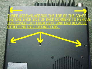
Disassembly:
- Face the front of the radio towards
you.
- Remove the three screws in a row
across the middle of the top of the radio.
- Remove the two screws at the top
rear (on the sides) of the radio.
- Pry the top cover off from the back.
- Disconnect the speaker at the
connector.
Modification:
- Near the top rear of the main
circuit board, there is an small, oblong metal can. Directly
below the right side of this can is two surface mount diodes
with a white silk-screened box around them. There is also
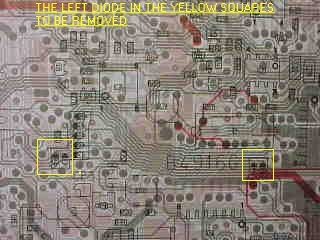
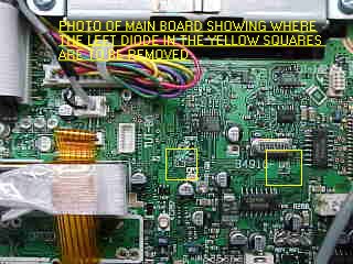
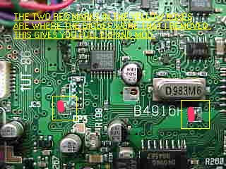
what appears to be a circuit board part number just to the
left of it (mine says B4916D). Remove the LEFT diode in the
box.
- To the left of this, there is a test
point marked CP3. Just to the left and above this test point
is another box with two *vertically* mounted surface-mount
diodes (Note: there is also a place for 5 more
*horizontally* mounted diodes, with 3 installed). Remove the
LEFT vertically oriented diode.
Reassembly:
- Reconnect the speaker.
- Put the top cover back on. Insert
the top cover tabs into the slots and lower into position.
- Replace all of the screws.
My radio did not require a reset, however I did lose all of my
channel memories. It seems to be able to transmit everywhere
except below .5 Mhz. I have not tested the power output at all
frequencies yet.
I hope this helps everyone who have been waiting patiently for
this mod.
Any comments can be directed to me:
Len - KC2ADV
...
Modification:
6. Near the top rear of the main circuit board, there is an small, oblong
metal can. Directly below the right side of this can is two surface mount
diodes with a white silk-screened box around them. There is also what
appears to be a circuit board part number just to the left of it (mine
says B4916D). Remove the LEFT diode in the box.
7. To the left of this, there is a test point marked CP3. Just to the left
and above this test point is another box with two *vertically* mounted
surface-mount diodes (Note: there is also a place for 5 more *horizontally*
mounted diodes, with 3 installed). Remove the LEFT vertically oriented
diode.
For first, my circuit board part number is B4916F, i don't understand
you what diodes i must cut off, explain me, my smd diodes looks like
this:
                              O<>O 7
                              O    O 6
                              O<>O 5
  J25                       O<>O 4
                              O<>O 3
                     O   O                                           O   O
                   1[]    [] 2                         B4916F   8[]   []9
                     O   O                                           O   O
                                 CP3
                                <__]


Diodes: 1,2,3,4,5,7,8,9 are installed
Diode: 6 is not installed
My version is with Tone 1750Hz, European i think, RX
30kHz-200MHz, TX in amateur bands only, the serial number if
needed is: 02101 buyed in 18.06.97 as new in Poland.
Sorry for my bugs.
Can You type me what diodes ? I think 1 and 3.
Rafa´ SP6-1313WR
Info on the diodes from another European user:
    d129
    ---- (d111 none)
    d112
    d113
    d114

d d                         d d
1 1                         1 1
1 1                         1 1
6 5                         8 9
D116 and D118 are responsible for out
of band TX. D115 and D119 enables RX from 30KHz to 200MHz. D113
is responsible for 6M RX and D114 is responsible for 6M TX. I do
not have info about D129 and D112. |
|
I have tried some special buttons on
IC706mkII:
Push TS and DISPLAY while power up and you will see a strange
power on check.
Push P.AMP/ATT and RIT/SUB while power up and you will be able
to see SHIFT-ADJ on your 706mkII. Dont know what this is for,
recalibrating ?
I think that these things even works on the older version of
706, dont know.
|
|
| |
TX range
expansion for IC-706MKIIG |
|
| |
|
|
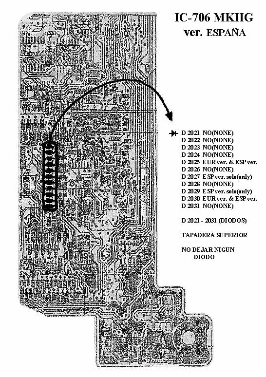
TX range expansion is very simple. On MAIN
BOARD under speaker near Xtal you can see two rows of solder
dots for SMD components. Only on position 10 (from left) is
diode (D2030), which is necessary to remove. Thats all. After
connecting power radio will be reseted and TX range is expanded.
|
|
| |
Expand
only mod for the IC-706MkII |
|
| |
|
|
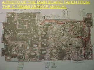
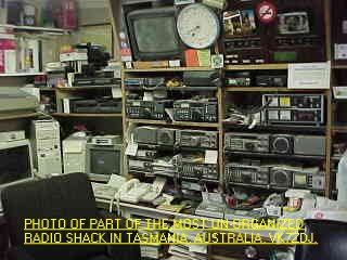
HI ALL, as an owner of
a IC-706MkII, I have noticed that there is no detailed photos of
how to go about the mods on any of the mod sites, so I pulled my
radio out of the car and I have taken some photos of the only
mod that I was interested in doing to my
radio,............EXPAND RX /TX.
I hope that the photos will help all new owners and or old ones
that have not been game enough to tackle the mod, its quite a
simple mod to do as long as you have good quality desoldering
equipment, if not then do not attempt it, take it to someone
that has the gear.
If you follow the text file on this page by "Len SantaMaria,
KC2ADV"
headed,.......Icom 706 MkII Extended Transmit Mod and use my
photos as a reference then I do not think you can go wrong, my
radio works like magic.
PLEASE NOTE THAT THESE MODS WERE DONE TO AN AUSTRALIAN
IC-706MkII RADIO,........AS FAR AS I CAN TELL THERE IS NO
DIFFERENCE BETWEEN MY RADIO AND THE AMERICAN MODEL, IF ANYONE
FINDS THIS NOT TO BE CORRECT THEN I AM SORRY BECAUSE I CANNOT
HELP YOU.
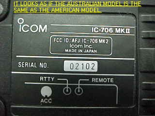
This information and photos was supplied by David
Spicer,VK7ZDJ.
|
|
| Here is som tips take
from www.gdierking.de/706/
Tipp: 1
Wenn Sie ausserhalb der Amateurbänder für Messzwecke ein
Sendesignal benötigen - einfach die kleine Diode D2030,
Mainunit, oben, ganz rechts in der Reihe, herausnehmen. Eigene
Menuedaten wieder einfügen.
Tipp: 2
Mehr Dynamik in der Modulation bekommt man durch Einstellen des
kleinen Widerstandstrimmer, direkt hinter der Frontwand, links,
neben dem Quarzfilter auf der Mainunit, oben.
Einstellen: Menue, Modulationspegel auf 1, den Buchstaben
"A" lange ins Mikrofon sprechen und gleichzeitig den
Trimmer auf maximale HF einstellen. Wenn das HF-Signal abreisst
- den Trimmer wieder etwas zurück drehen.
Tipp: 3
Die Sendeleistung auf HF kann mit dem Trimmer "HF TX power
adj." leicht auf 150 W und auf 2 m mit dem Trimmer
"144 MHz TX power adj." auf ca. 90 W eingestellt
werden. Siehe Seite 63 in der Bedienungsanleitung.
|
|
| |
IC-706,
MKII, MKIIG xmit mods - tip |
|
| |
|
|
| Ref Xmit Mods for 706s
shown above
The xmit expand mod for the IC-706,
MKII, MKIIG require removing very small diodes, these diodes are
about the size of a flea, and require the use of very small
tools.
I have done mods before but these are
difficult.
After lots of thought I did my mod with an x-acto knife. I
needed a magnifying glass and a new blade for the x-acto knife. I
cut just the solder on one side of the tiny diode, making sure
that is all I cut, then pushed up on the diode, the other side
breaks loose from the board. I cut both diodes this way and it
was easy and worked fine.
I could not find a soldering iron small enough to fit into tiny
space available. Good luck.... Emory
|
|
| |
IC-706 10
watt tune modification/An Icom IC706 Tune Trigger |
|
| |
|
|
| Some assembly required
The ICOM IC-706 has a nifty feature
built in to help the operator tune the HF antenna SWR. By
pushing the TUNE button on the front panel, the radio switches
to CW mode and transmits a 10 Watt carrier. This state last for
approximately 10 seconds or the operator can terminate sooner by
pushing the button again. This was designed to work with the
Icom automatic antenna tuners. There have been a few circuits
developed to fool the 706 into thinking there is a Icom tuner
attached and produce the same tuning signal which can be used
with a manual antenna tuner or many automatic tuners, some get
quite complex.
Well, being the cheap guy I am, and
being one to tinker, I felt there had to be a simple way to do
this. I began reading the various postings on the Internet. I
went back to an e-mail exchange I had with Ed, W1AAZ in early
April 1999 on Vartel's ICOM 706 Discussion Group. Ed explained
the functions of the TKEY and TSTR pins on the "AH-3"
connector on the 706.
The outcome was a simple RC circuit
which I have built right on a Molex connector which plugs into
the AH-3 jack on the back of the IC706.
CONSTRUCTION:
The (+) side of C is connected to the 13.8VDC pin. The (-) side
connected to TSTR and TKEY which are connected together.
Resistor R is in parallel with C. Below is a diagram of the AH4
connector on the back of the IC706 where the < indicates the
pointy end of the connector (Pin 1 = TKEY). You can buy the
Molex connector at Radio Shack (#274-0224).
	< TKEY  TSTR  13.8V  GND ]
	   |_____|       |
	      |    R     |
	      +--\/\/\/--+
	      |      +   |
	      +----)(----+
	           C
The values I use are C=1000uF 16WV
R=92K Ohms 1/8 Watt which result in 15 seconds of tune time. As
you can see, these are tied in parallel. If you want to use a
physically smaller capacitor such as 440 uF, you can adjust the
time by raising R. The extreme values I found are:
2K<R<3.3M Ohms
10uF<C<4700uF.
OPERATION:
Be sure to read the manual about the various Initial Settings
that can affect the operation with a tuner connected, otherwise
you may go into the TUNE mode every time you change frequency or
push the PTT.
Turn off the radio and plug in the
unit. Make sure you have some sort of load on the HF antenna
connector. Turn on the IC706, the radio sees TSTR is high during
boot up and thinks there is a tuner connected. Be sure the meter
is in the SWR mode. Push the TUNE button. The TUNE light should
flash counting the seconds and stay lit when finished, as stated
in the manual. You may interrupt the cycle by pressing TUNE
again.
If you terminate the TUNE mode early by
pressing the button again, you must wait for the remainder of
the time-out period to re-start. If you don't then the cycle is
started over again when you press TUNE and you still must wait,
but longer. This is why I have opted for 15 seconds instead of a
possible 30 seconds. One way to reset the timer is by powering
the IC706 off then on.
I have noticed false triggering when
the supply voltage AT THE IC706 POWER CONNECTOR drops during
transmit and C has not yet totally discharged. This is caused by
the TKEY voltage dropping through the trigger point because the
supply voltage drops while C is discharging. This lead me to
upgrade my power supply cable so there is less voltage drop when
I transmit.
ALTERNATE DESIGN:
You can eliminate the capacitor and the TKEY to TSTR connection
if you want to manually trigger the IC706 into TUNE. You do need
the pull-up resistor between TSTR and 13VDC to make the radio
think there is a tuner present during power up. Then ground TKEY
to trigger the TUNE mode as long as TKEY remains grounded.
|
|
| |
Mods
IC706 MKIIG por
EA1DOU
(ver. Española) |
|
| |
|
|
|
|